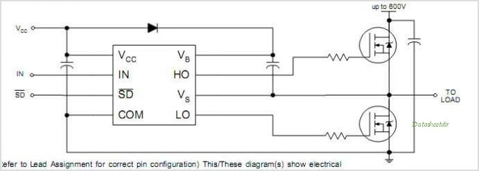
Full Bridge Mosfet Driver

The ISL6700 is an 80V/1.25A peak, medium frequency, low cost, half-bridge driver IC available in 8-lead SOIC and 12-lead QFN plastic packages. The low-side and high-side gate drivers are independently controlled and matched to 25ns.
This gives the user maximum flexibility in dead-time selection and driver protocol. Undervoltage protection on both the low-side and high-side supplies force the outputs low. Non-latching, level-shift translation is used to control the upper drive circuit. Unlike some competitors, the high-side output returns to its correct state after a momentary undervoltage of the high-side supply. • Drives 2 N-Channel MOSFETs in Half-Bridge Configuration • Space Saving SO8 and Low RC-S QFN Packages • Phase Supply Max Voltage to 80VDC • Bootstrap Supply Max Voltage to 96VDC • Drives 1000pF Load with Rise and Fall Times Typ.
Renesas' large portfolio of driver products comprises half-bridge, full-bridge, low-side, and synchronous buck MOSFET drivers. The bridge driver products handle voltages up to 100V, with industry-leading gate rise and fall times and exceptional input-to-output propagation delay performance. MIC4606, In Production, No, $1.43, Synchronous, Full Bridge Driver, Dual Inputs, Single PWM, 1.0/1.0, 10/6, 35/35, 20/20, 1000 pF in 35 ns, Adaptive Dead Time.
15ns • TTL/CMOS Compatible Input Thresholds • Independent Inputs for Non-Half-Bridge Topologies • No Start-Up Problems • Low Power Consumption • Wide Supply Range • Supply Undervoltage Protection • QFN Package • Compliant to JEDEC PUB95 MO-220 QFN • Quad Flat No Leads - Package Outline • Pb-Free Available (RoHS Compliant). Sapr gracia torrent pdf.
Introduction In the of the series we’ve gone through the high-level design decisions that you have to make when designing an H-Bridge, and we’ve discussed the considerations for selecting the MOSFETs and the catch diodes that will make up the bridge. In this article I will go through the available options for drive circuits. We will discuss the trade-offs between them and what influences the various parameters of the drive circuits. You will take the most out of this write-up if you are already fairly familiar with H-Bridge basics, so if you aren’t, I suggest you read the of the series first. Understanding of the various drive-modes will also be useful, so reading the, the and the articles isn’t a waste of time either, though those pieces go into quite a bit of more detail than what is needed to follow this text. To make referencing easier, let’s review the H-Bridge circuit: and our motor model: Drive circuitry The drive circuitry for an H-Bridge is basically the electronics that sits between the PWM (and potentially other) digital control inputs and the MOSFET gates.

Thank you very much. Really very informative! I just have a question about N-MOS high-side drive circuits: Is it possible to apply a second voltage higher than V_bat from a second power supply. Dsch 35 software free download pc. I mean if the main power supply is 40v,there should be another one higher no more than 20v (55v) to drive the N-MOS high-side gate?I did the simulation and it worked. I will try that sooner in real.
While googling I didn’t find info about this. Does it have any disadvantages apart cost?? Like in turn off, turn on shoot through? Short answer: Don’t try it! It will blow your FET. Long answer: Well, actually it is possible to do and for low voltages that’s quite common.